Antenna Range Technical Data
General Characteristics of Mesa Antenna Ranges
Range Name
| Range Length |
Operating
Frequency | Measurements | Test Positioner |
212 East | 0-130 ft. | UHF to K-Band | Radiation patterns and gain | Polarization with traverse table over azimuth over elevation on cart |
212 West | 0-650 ft. | UHF to K-Band | Radiation patterns and gain | Polarization over azimuth over elevation on cart, 20 ft mast |
256 East | 0-68 ft. | UHF to K-Band | Radiation patterns and gain | No positioner in place at this time |
40 ft. Anechoic Chamber | 19 ft. Test Area | X to W-Band | Radiation pattern and gain using cylindrical near field techniques | Azimuth |
60-ft Anechoic Planar Near-field | 13 ft. x 30 ft. scan area | L-band to Ka-band | Radiation pattern and gain using planar nearfield technique | Fixed antenna mount for planar scan. |
60-ft Anechoic Spherical Near-Field | Up to 7.6ft scan radius | L-band to Ka-band | Radiation pattern and gain using spherical near-field technique | Azimuth over elevation spherical scan system. |
1200 ft. Range | 1200 ft. | UHF to W-Band | Radiation patterns and gain | Azimuth over elevation over azimuth |
3000 ft. Range | 3000 ft. | UHF to W-Band | Radiation patterns and gain | Heavy duty polarization over elevation over hydraulic elevation over azimuth |
Large Bell Jar Breakdown Facility | 6 ft. Test Cell | UHF to K-Band | RF High Power breakdown | 6 Ft. Bell Jar in anechoic screened room |
Small Bell Jar Breakdown Facility | 14" cell | UHF to Ka-Band | RF High Power breakdown | 14" DIA x 20" Bell Jar |
243A | 15 ft. | X to Ka-Band | Radiation patterns and gain | Polarization over elevation with traverse table over azimuth |
243B | 0-18 ft. | X to K-Band | Transmission & reflection for Frequency Selective Surfaces | Approx 1 m square zone |
Approximate Maximum Test Antenna Aperture Size -- Nearfield Ranges
60-ft Anechoic Chamber
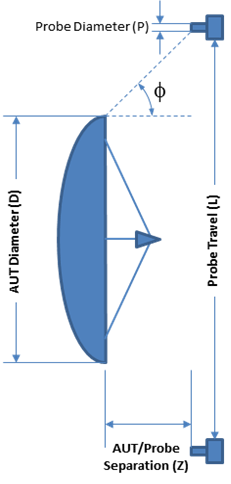
The planar nearfield range located in the 60-ft chamber collects data over a rectangular region in front of an Antenna Under Test (AUT) by using a mechanically actuated probe. Referring to the figure at right, the AUT size D, probe travel L, AUT/Probe separation Z and probe size P determine the angle Φ according to the equation L=D+P+2Z tan(Φ). The calculated far-field pattern of the antenna will be accurate in the region between ±Φ. The maximum probe travel L is 30-ft in the horizontal direction and 13-ft in the vertical direction. Typical AUT/Probe separation Z is between 3-6 wavelengths and probe size P~1 wavelength. A far-field pattern region of Φ=70 degrees is typical.
The spherical scan positioner located in the 60-ft chamber is used to perform spherical nearfield testing by collecting data over a spherical region around the AUT in conjunction with the NSI-MI near-field to far-field software. This method provides complete angular coverage (except for a small exclusion region at the antenna mounting bracket). The maximum AUT size for spherical measurements 1.4 m in diameter and a weight of 75 Kg.
40-ft Anechoic Chamber
The cylindrical nearfield range located in the 40-ft chamber collects data over a cylindrical region surrounding an Antenna Under Test (AUT) by using a mechanically actuated probe to scan in the vertical direction and a turntable to rotate the AUT. This method provides complete angular coverage in the azimuth direction, but does not cover conical exclusion regions above and below the AUT. The angle Φ that defines these exclusion regions is determined as described above for the planar nearfield system. For the cylindrical scanner, probe travel L is 150 inches. The maximum antenna size is constrained by the distance from the turntable’s axis of rotation to the chamber walls, approximately 9 feet.

256 East | 212 East | 212 West | 1200 Ft. | 3000 Ft. | 243 | ||
0.5 GHz | 2.5 m | 3.5 m* | 7.8 m* | 10.5 m* | 17.0 m* | 1.2 m* | |
1.0 GHz | 1.8 m | 2.5 m | 5.6 m* | 7.5 m* | 12.5 m* | 83 cm* | |
2.3 GHz | 1.2 m | 1.6 m | 3.7 m | 4.9 m* | 8.1 m | 54 cm* | |
8.5 GHz | 60 cm | 90 cm | 1.9 m | 2.6 m | 4.2 m | 28 cm | |
16.5 GHz | 40 cm | 60 cm | 1.4 m | 1.8 m | 3.2 m | 20 cm | |
30.0 GHz | 33 cm | 46 cm | 1.0 m | 1.4 m | 2.2 m | 15 cm | |
60.0 GHz | 23 cm | 32 cm | 73 cm | 98 cm | 1.6 m | 11 cm | |
95.0 GHz |
| 1.4 m | |||||
| *May not be practical, each case will need to be evaluated. | |||||||
